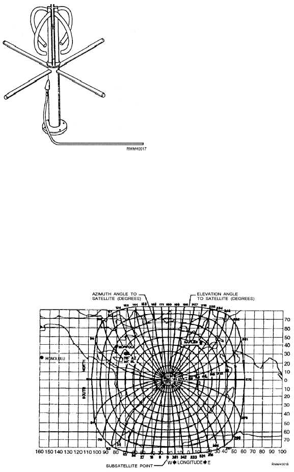
Figure 2-28.—AS-2815/SSR-1 antenna physical configuration.
Figure 2-26. This antenna is normally mounted
horizontally.
BROADBAND ANTENNAS
Broadband antennas for HF and UHF bands have
been developed for use with antenna multicouplers.
Therefore, several circuits may be operated with a
single atenna. Broadband antennas must be able to
transmit or receive over a wide frequency band.
HF broadband antennas include the 35-foot twin
and trussed whips, half-cone, cage, and a variety of fan-
designed antennas. The AT-150/SRC UHF antenna in
figure 2-26 is an example of a broadband antenna.
SATCOMM ANTENNAS
The antennas shown in figures 2-27 and 2-28 are
used for satellite communications. The 0E-82C/WSC-
1(V) antenna (figure 2-27) is used with the AN/WSC-3
transceiver and designed primarily for shipboard
installation. Depending upon requirements, one or two
antennas may be installed to provide a view of the
satellite at all times. The antenna is attached to a
pedestal. This permits the antenna to rotate so that it is
always in view of the satellite. The frequency band for
receiving is 248 to 272 MHz and for transmitting is 292
to 312 MHz.
The AN/SRR-1 receiver system consists of up to
four AS-2815/SSR-1 antennas (figure 2-28) with an
amplifier-converter AM-6534/SSR-1 for each antenna.
The antennas are used to receive satellite fleet
broadcasts at frequencies of 240 to 315 MHz. The
antenna and converters are mounted above deck so that
at least one antenna is always in view of the satellite.
The newer satellite systems use the SHF band. One
of the major advantages of these systems is that they use
a very small parabolic antenna measuring only 12
inches in diameter.
A satellite antenna must be pointed at the satellite to
communicate. We must first determine the azimuth
(AZ) and elevation (EL) angles from a fixed location.
Figure 2-29 illustrates how these angles are derived,
Figure 2-29.—Equatorial Satellite Antenna Pointing Guide.
2-23


